Tuesday, June 4, 2019

Fibre Channel SAN Part 4 – Redundancy and Multipathing

Fibre Channel Redundancy


Servers' access to their storage will invariably be mission critical for the enterprise, so we're not going to want to have any single points of failure. Redundant Fibre Channel networks should be put in place, known as Fabric A and Fabric B, or SAN A and SAN B. Each server and storage system host should be connected to both fabrics with redundant HBA ports.

Fibre Channel switches distribute shared information to each other, such as domain IDs, the FCNS database, and zoning. When we configure zoning in a fabric, we only need to do it on one switch, and it will then be automatically distributed to the other switches from there. This makes things more convenient for us, but there's also a potential downside here as well, because if we make a misconfiguration it's going to be replicated between all the switches in the fabric. If an error in Fabric A was able to propagate to Fabric B, this would bring down both fabrics, and it would drop the server's connection to their storage. This would be disastrous.

For this reason, switches in different sides of the fabric are not cross-connected to each other. Both sides of the fabric are kept physically separate. This is different to how we do things in Ethernet LAN networks where we do usually cross-connect our switches.

In Fibre Channel networks, we have two fabrics, Fabric A and Fabric B. End hosts (including the storage system) are connected to both fabrics, but the switches are not. Switches are dedicated to either Fabric A or Fabric B.

In the example below, Server 1 has two HBA ports for redundancy. The first port is connected to Fabric A and the second port is connected to Fabric B.

Redundant SAN Fabrics

I do the same on my storage system which has also got redundant HBA ports. One is connected to Fabric A and the other is connected to Fabric B.

The two fabrics are kept strictly physically separate from each other which is signified that the big red line up the middle of the diagram. Hosts are connected to both fabrics, but the fabrics are kept physically separate from each other. This means that if I have a misconfiguration in Fabric A, Fabric A could go down, but that misconfiguration cannot be propagated to Fabric B. My server would lose connectivity to its storage over Fabric A, but it can still get there over Fabric B so we don't have a complete outage.

Okay, but wait. We're going to have at least two controllers for redundancy of our storage system, so our network topology is actually going to look more like the diagram below.

Redundancy - 2 Controllers

As before, we’ve got the Fabric A and the Fabric B networks which are kept physically separate from each other. Server 1 and Server 2 are connected to both fabrics. Now up at the top, I've got two separate storage system controllers for redundancy. The controllers, just like the servers, act as end hosts, so my storage controllers are connected to both Fibre Channel fabrics.

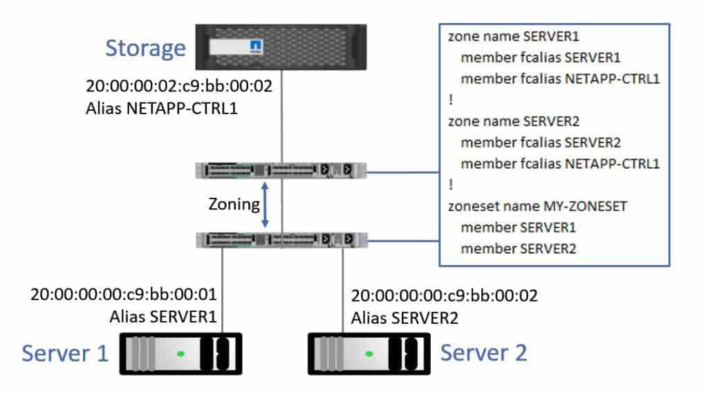
On a switch in Fabric A, I configure a zone for Server 1 which includes member fcalias S1-A (the HBA port on Server 1 which is connected to the Fabric A network), member fcalias Controller 1-A (the HBA port on Controller 1 which is connected to the Fabric A network) and member fcalias Controller 2-A (the HBA port on Controller 2 which is connected to the Fabric A network). Both Controller 1 and Controller 2 are connected to my Fabric A network, and my server can reach its storage through either controller.

Server 1 Zoning
Server 1 Zoning

Also, on that same Fabric A switch, I'll configure a zone for Server 2 which includes member fcalias S2-A (the HBA port on Server 2 which is connected to the Fabric A network), member fcalias Controller 1-A (the HBA port on Controller 1 which is connected to the Fabric A network) and member fcalias Controller 2-A (the HBA port on Controller 2 which is connected to the Fabric A network). Note that the Server 2 zone contains the same HBA ports on the  controllers that Server 1 is also connecting on, it’s just the server which has changed.

Server 2 Zoning
Server 2 Zoning

I then tie it all together into a zone set. I’ve named my zone set Zoneset-A and it includes zone members Server1 and Server2. I configure that on one of the two Fabric A switches, and it will propagate it to the other switch, which saves me having to do a duplicate configuration on both.

Fabric A Zoneset
Fabric A Zoneset

I also need to configure my Fabric B switches. I configure a zone for Server 1 which includes member fcalias S1-B (the HBA port on Server 1 which is connected to the Fabric B network), member fcalias Controller 1-B (the HBA port on Controller 1 which is connected to the Fabric B network) and member fcalias Controller 2-A (the HBA port on Controller 2 which is connected to the Fabric B network).

Server 1 Zoning - Fabric B

I also need a zone for Server 2, so I do a similar configuration there. The Server 2 zone includes member fcalias S2-B (the HBA port on Server 2 which is connected to the Fabric B network), member fcalias Controller 1-B (the HBA port on Controller 1 which is connected to the Fabric B network) and member fcalias Controller 2-A (the HBA port on Controller 2 which is connected to the Fabric B network).

Server 2 Zoning - Fabric B

I then tie it all together in my Fabric B zone set. I create a zoneset named Zoneset-B which includes member zone Server1 and Server2. I configure that on one of the two Fabric B switches, and it will propagate it to the other Fabric B switch. That takes care of my zoning on my switches.

Fabric B Zoneset
Fabric B Zoneset

Each server has four redundant paths to the storage system. Over Fabric A to Controller 1, over Fabric A to Controller 2, over Fabric B to Controller 1, and over Fabric B to Controller 2.

LUN Masking


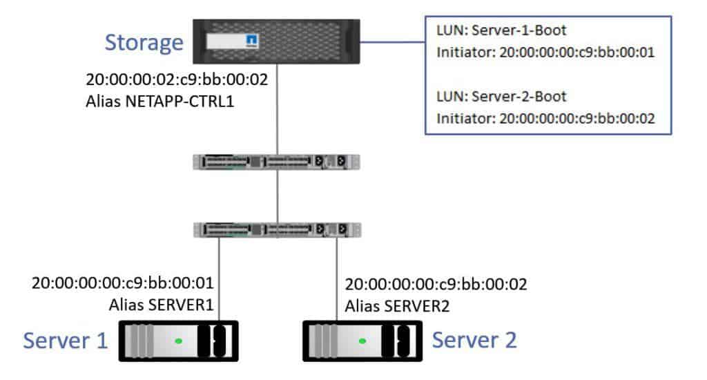
As well as configuring zoning on the switches, I also need to configure LUN masking on the storage system.

LUN Masking
LUN Masking

On my storage, I have boot LUNs for Server 1 and for Server 2.

I configure the LUN Masking so that Server 1 can use either of its HBA ports to connect to its LUN. S1-A is an alias for its WWPN which connects to Fabric A, and S1-B is an alias for its WWPN which connects to Fabric A. Both of these aliases are added to the LUN Masking group which is allowed access to the Server 1 LUN. Server 1 is allowed to connect over both Fabric A and Fabric B.

For the Server 2 boot LUN, I do the same thing. I configure the members of its LUN Masking group to be the WWPN aliases Server 2-A and Server 2-B.

Target Portal Groups


The next topic to discuss is TPGs, Target Portal Groups. All of the ports on the storage system which initiators can access their storage through are members of a Target Portal Group. TPGs can be used to control which ports initiators can access the storage target on. If you needed to, you could configure separate TPGs to dedicate a set of ports on your storage system to only your mission critical servers. On most storage systems, all ports will be added to a single TPG by default through which all initiators can access their storage.

In the example below, ports Controller 1-A, Controller 1-B, Controller 2-A, and Controller 2-B are added to a Target Portal Group. Each of those ports will have its own unique WWPN which is in the TPG, and the hosts will learn that they can connect to their storage through any of them.

Target Portal Groups

Asymmetric Logical Unit Assignment


ALUA is used by the storage system to tell the client which are the preferred paths for it to use. Direct paths to the storage system node which owns the LUN are marked as optimized paths. Other paths are marked as non-optimized paths.

Let's look at how this is going to work. We've got the same example we were looking at earlier, where I've got a storage system which is made up of two nodes, Controller 1 and Controller 2. Controller 1 owns the disks where the LUN for Server 1 is currently located.

ALUA
ALUA

Server 1 can get to its LUN through either Controller 1 or Controller 2, but it would be better for it to go to Controller 1 because that is a direct path. The storage system can give the server all of this information, let it know all of the paths that it can take to get there, and which are the preferred paths. It uses ALUA to do that.

Server 1 learns about Optimized Path 1, which is going through Fabric A and terminates on HBA Controller 1-A.

ALUA Optimized Path 1

It also learns about Optimized Path 2, which is going through Fabric B and which terminates on HBA Controller 1-B.

ALUA Optimized Path 2

Path 1 and Path 2 are optimized paths because they go to Controller 1, which is where the LUN is.

The server will also learn about Non-Optimized Path 3, which goes through Fabric A and terminates on the HBA Controller 2-A.

ALUA Non-Optimized Path 3

And Non-Optimized Path 4, which goes through Fabric B and which terminates on Controller 2-B.

ALUA Non-Optimized Path 4

The server has four different paths that it can take to get to its storage, and two of them are better optimized paths.

During the login process, initiators will detect ports available to connect to their storage on in the Target Portal Group, and ALUA will notify which are the preferred paths.

Multipathing


Multipathing software on the initiator will choose the path or paths to take to the storage. All popular operating systems (all flavors of Windows, Unix, Linux, VMware etc.) have multipathing software which supports active/active or active/standby paths. The client will automatically fail over to an alternate path if the one it is using fails.

Considering our example where we had the two optimized paths and the two non-optimized paths, using our multipathing software on the client we could choose to do active/active load balancing over both optimized paths, or we could do active/standby, where we send the traffic over one of the optimized paths, and if it goes down we fail over to the other optimized path.

Popular manufacturers for HBAs are Emulex and Qlogic, and they both have their own multipathing software which is installed and configured on the client.

Summary


As you've seen, client connectivity to SAN storage is fundamentally different to how Ethernet networking works. I already had a lot of experience in Ethernet networking before I learned storage, and I found this pretty amazing. In Ethernet, if you want to connect a client to a server, you have to point the client at the server's IP address. With Fibre Channel, because of the login process, the client will automagically detect its LUNs.

In Ethernet networking, all the routing and switching decisions are handled by network infrastructure devices. In SAN storage, multipathing intelligence is enabled on the client end host.

Fibre Channel SAN Part 3 – Fabric Login

The Login Process

FLOGI


When a server's or storage system's HBA port powers on, it will send a Fabric Login request (FLOGI) which includes its WWPN, to the fibre channel switch it is directly plugged into. The switch will then assign it a 24-bit FCID, which is the Fibre Channel ID address. The host is basically saying "Hey, this is my WWPN. Please assign me an FCID, so that I can communicate on the fibre channel network."

The FCID assigned to hosts is made up of the switch's Domain ID and the switch port that is plugged into. The FCID is similar to an IP address in Ethernet. It's used by Fibre Channel switches to route traffic between servers and their storage. Switches maintain a table of FCID to WWPN address mappings and what port the host is located on.

The Fibre Channel switches share information with each other. Every switch in your network learns about the Domain IDs of all the other switches. It also learns about the WWPNs of all the hosts that are attached to the network, and the FCID those WWPNs are mapped to. Based on the FCID, it knows the Domain ID of the switch that each host is plugged into (because the first part of the FCID is the Domain ID). Because they have all this information, they're able to switch traffic between the hosts.

Here's a diagram of the Fabric Login process working. When Server 1 powers on, its HBA port will send a a FLOGI to the switch that it is attached to. The switch will assign it an FCID. If I now ran a show FLOGI database command on that switch, I would see the interface that the server is plugged into, and its FCID, and its WWPN. In the example here I've configured the alias SERVER1 for the WWPN which is also reported.

FLOGI Fabric Login
FLOGI Fabric Login

The same thing happens with our storage system up at the top of the diagram. When it powers on, its HBA port will send a FLOGI to the switch that it's plugged into. The switch will assign that port an FCID, and if do a show FLOGI database on that switch, we'll see the interface that the storage is plugged into, its FCID, its WWPN, and the alias if one is configured (the alias NETAPP-CTRL1 has been configured in our example).

The Fibre Channel Name Service


The fibre channel switches share the FLOGI database information with each other using FCNS, the Fibre Channel Name Service. Each switch in the network learns where each WWPN is, what its FCID is, and how to route traffic there.

The show FLOGI database command on Cisco switches will only work on the switch where the clients are directly plugged into. The switches share that local information with each other through FCNS. If we do a show FCNS database on a Cisco switch, we will see the FCID and the WWPN of all of the hosts that are in our network. Because the FCID is derived from the Domain ID, which is how we identify our switches, the switches now know how to route traffic to any host in the network.

FCNS database
FCNS database

Port Login


After the FLOGI Fabric Login process is complete, the initiator will send a Port Login (PLOGI). Based on the zoning configuration on the switch, the host will learn its available target WWPNs on its storage.

In the example below, Server 1 sent a FLOGI and was assigned its FCID. When that process is complete, it will send a PLOGI to its locally attached switch. The switch will check its zoning configuration and allow the server to talk to its storage.

Port Login
Port Login

Process Login


Finally we have the PLRI, the Process Login. The initiator host will send a PLRI Process Login request to its target storage. The storage system will grant access to the host to its LUNs, based on its configured LUN masking.

PLRI Process Login
PLRI Process Login

Fibre Channel SAN Part 2 – Zoning and LUN Masking

Zoning


For security, zoning is configured on our Fibre Channel switches to control which Fibre Channel ports are allowed to communicate with each other. We allow the ports on the client hosts (the initiators) to talk to the ports on the storage system (the targets). Initiators are not allowed to communicate with each other over the Fibre Channel network. This increases security and reduces traffic, which makes the Fibre Channel network more reliable and stable.

Popular manufacturers of Fibre Channel switches are Cisco and Brocade. The example below is for a Cisco switch, but Brocade uses a similar configuration.

In the example, I've got a couple of servers down at the bottom of the diagram which are clients of the storage system up at the top. Aliases are used to map the long WWPN name to a more convenient alias name chosen by the administrator. I've configured aliases on my Fibre Channel switch for the WWPNs on the servers and on the storage system.

Fibre Channel Zoning


Fibre Channel Zoning
Separate zones are configured for each separate set of connectivity requirements. I configure a zone which enables Server 1 to communicate with the storage system, and a separate zone which allows Server 2 to communicate with the storage system.

Zone name SERVER1 includes member fcalias SERVER1 and member fcalias NETAPP-CTRL1. This allows SERVER1 to talk to its storage.

Zone name SERVER2 includes member fcalias SERVER2 and member fcalias NETAPP-CTRL1. This allows SERVER2 to talk to its storage.

Then, I group all of those zones together into a zone set and apply that on the switch. I've named the zoneset MY-ZONESET, and it includes zones SERVER1 and SERVER2.

With this configuration, Server 1 can talk to its storage and Server 2 can talk to its storage. The two servers can't talk to each other over the fibre channel network because they’re not included in a zone with each other.

Note: This is a simple example to make initial learning easier. Typically we’ll have at least two storage controllers and switches for redundancy. Please see the final part 3 of this series where I cover redundant fabrics for a more realistic example of how zoning is configured in real world deployments.

LUN Masking


As well as configuring zoning on our switches, we also need to configure LUN masking on the storage system. It's critical that the right LUN is presented to the right host. If the wrong host was able to connect to a LUN then it would be liable to corrupt it.

The zoning on the switches make sure that the servers can't talk to each other, but they can talk to the storage. So how do I make sure that they can't connect to each other's LUNs? That's where LUN masking comes in.

Zoning on the switches prevents unauthorized hosts from reaching the storage system, and it prevents hosts from talking to each other over the fibre channel network, but it doesn't prevent a host from accessing the wrong LUN once it gets to the storage system. LUN masking is configured on the storage system to lock a LUN down to the host or hosts who are authorized to access it. To secure your storage, you need to configure zoning on your switches and LUN masking on your storage system.

Here's an example of how we would configure LUN masking. Server 1 and Server 2 are both diskless servers. I've configured Boot LUNs for both Server 1 and Server 2 on the storage system. For my Server 1 Boot LUN, the only initiator that can connect to that is Server 1's WWPN. And for the Server 2 Boot LUN, the only initiator that can connect to that is Server 2's WWPN. This prevents the wrong server connecting to and potentially corrupting the other server’s LUN. I could also have used aliases here rather than typing in the WWPN in my configuration.

LUN Masking

LUN Masking

Switch Domain IDs


The next thing to talk about is Switch Domain IDs. Each switch in in the fibre channel network will be assigned a unique Domain ID. The name can be a bit confusing, because if you’re like me, you’d think a Domain ID would be an ID number which represented the entire domain of switches, but it doesn't mean that at all. The Domain ID is actually a unique ID for each individual switch in that fibre channel network.  The Domain ID is a value from 1 to 239 on both Cisco and Brocade switches.

One switch in the network will be automatically assigned as the Principle Switch. It is in charge of ensuring each switch in the network has a unique Domain ID.

Each switch learns about the other switches in the network and how to route to them, based on their Domain ID.

Fibre Channel SAN Part 1 – FCP and WWPN Addressing

SAN Terminology


Before we start getting more in depth on Fibre Channel, let me give you some basic general SAN terminology.

LUN stands for Logical Unit Number. The LUN represents a logical disk that will be presented to a host. The client connects to its LUN and uses it as if it was a local hard drive. LUNs are specific to our SAN, not our NAS protocols.

The client is known as the initiator and the storage system is known as the target.

The Fibre Channel Protocol


FCP, the Fibre Channel Protocol, is used to send the SCSI commands over the Fibre Channel network. If your client had a local hard drive, it would send SCSI commands to that local hard drive. With SAN, it's sending the SCSI commands, but over a network now.

Fibre Channel is Lossless


Fibre Channel is a very stable and reliable protocol which is one of the main reasons it remains very popular with old school storage engineers.

Ethernet networks are lossy. With TCP, the sender sends traffic to the receiver, and the receiver will periodically send acknowledgements back. If a sender doesn't get an acknowledgement back, then it knows that the traffic was lost in transit and it will resend the traffic.

UDP is best effort, without acknowledgements. It’s up to the higher application layers to deal with any lost traffic.

Fibre Channel is lossless, unlike TCP and UDP. The buffer-to-buffer credits flow control mechanism is built into the protocol to ensure frames are not lost.

Fibre Channel Speeds


Fibre Channel currently supports bandwidths of 2, 4, 6, 8 and 16 Gbps. Not all hardware supports the higher speeds, so the speed you’ll get depends on the equipment you've got deployed.

Fibre Channel Networking


Fibre Channel is different than Ethernet at all layers of the OSI stack, including the physical level, so it requires dedicated adapters, cables and switches. You can't use an Ethernet network card or an Ethernet switch for Fibre Channel. This is different than iSCSI, FCoE and our NAS protocols which do run over Ethernet.

(FCoE is a special case in that it uses an Ethernet network but still runs the Fibre Channel protocol which requires lossless traffic, so it can’t use standard Ethernet adaptors and switches.

In the example here, the host in the middle of the diagram is a web server and its client, at the top, is going to be accessing a web page on that web server. The client will access the server over the normal Ethernet local area network. Then to fetch the web page, the server will connect to its storage over the Fibre Channel network.

Fibre Channel FCP and WWPN


For the local area network which connects it to its client, the server uses standard Ethernet NIC (Network Interface Card) ports. Typically we will use two ports for redundancy, either on the same or separate physical cards.

For the storage area network which connects it to its storage, the server has standard Fibre Channel HBA (Host Bus Adapter) ports. An HBA is the Fibre Channel equivalent of an Ethernet NIC. Again we will typically use two for redundancy.

Network Addressing – The WWN


Fibre Channel uses World Wide Names, WWNs, for its addressing. Both initiators and targets are assigned WWNs. The WWNs are 8 byte addresses that are made up of 16 hexadecimal characters. Here’s an example:

21:00:00:e0:8b:05:05:04

There are two types of WWN address: The WWNN and the WWPN. They both use the same format and look the same.

The WWNN World Wide Node Name


The World Wide Node Name (WWNN) is assigned to a host in the storage network. The WWNN signifies that individual host. The same WWNN can identify multiple network interfaces of a single network node. A host could have multiple HBAs, or multiple ports in an HBA.

You might sometimes see the WWNN also being referenced as the NWWN, the Node World Wide Name. WWNN and NWWN are exactly the same thing, just two ways of saying it.

The WWPN World Wide Port Name


Our hosts also have World Wide Port Names, WWPNs. A different WWPN is assigned to every individual port on a node. If we had a multi-port HBA in the same host, each port on that HBA would have a different WWPN. WWPNs are the equivalent of MAC addresses in Ethernet. The WWPN is burned in by the manufacturer of that HBA, and it's guaranteed to be globally unique.

Just like WWNNs can also be known as NWWNs, WWPNs are also sometimes known as PWWNs. Again it means the same thing.

Both the initiator (the client) and the target (the storage system) are assigned WWNNs and WWPNs on their Fibre Channel interfaces to enable them to communicate with each other.

We're primarily concerned with the WWPNs, not the WWNN, when we're configuring Fibre Channel networks.

Aliases


The WWPN is a big, long hexadecimal address. It isn’t obvious which system it’s on if we’re looking at the output of troubleshooting commands, and it’s easy to make a typo when we’re entering our configuration.

Aliases can be configured for the WWPNs to make configuration and troubleshooting easier. For example, we could create an alias named EXCHANGE-SERVER-PORT-1. Now when we’re configuring settings, we can specify the alias, rather than the WWPN. This is more convenient and makes it less likely that we're going to put in any typos. Also, the Alias will be shown in any troubleshooting output which makes it immediately obvious which system we’re looking at.

For Fibre Channel you're going to need to reference WWPNs in both the Fibre Channel switch and the storage system configuration. Aliases can be used on both of them.